DBMS — UT1 Notes
These notes answer the questions listed in UT1. They are based on the DBMS Module 1 PPT, Module 2 Notes PDF, and Module 2 question-support PPT in this folder.
How to write a long answer
Start with the definition, draw the diagram or notation, explain the main points, and finish with a suitable example. Underline key terms such as data integrity, data independence, cardinality, and referential integrity.
1. Purpose of a Database System
A database system is the combination of a database, a DBMS, the applications that access it, and the people who use it. Its purpose is to store and manage related data so that it can be accessed, updated, shared, and protected efficiently.
Main purposes
- Organised storage: Store large amounts of related data in a structured form.
- Efficient access: Retrieve required records quickly using queries and access methods.
- Easy maintenance: Insert, update, and delete data without rewriting the whole application.
- Reduced redundancy: Avoid unnecessary duplicate copies of the same data.
- Consistency: Ensure that the same data has the same correct value wherever it is used.
- Data sharing and concurrency: Allow many authorised users to work with the database at the same time.
- Security: Control users, roles, and permissions so that only authorised actions are allowed.
- Integrity: Enforce rules such as unique IDs, valid ranges, and valid references between tables.
- Backup and recovery: Restore data after accidental deletion, hardware failure, or another problem.
- Data independence: Allow storage or database-structure changes with minimal effect on applications.
flowchart LR
    U[Users and applications] --> D[DBMS]
    D <--> B[(Database)]
    D --> S[Security, integrity, backup and recovery]
Conclusion: A database system provides a controlled, reliable, secure, and efficient way to manage organisational data. Examples include banking, hospitals, universities, railway reservations, and e-commerce systems.
2. Types of Relationships
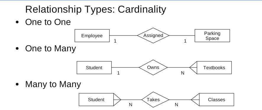
A relationship describes an association between two or more entities. Cardinality specifies how many instances of one entity can be associated with instances of another entity.
a. One-to-one (1:1)
Each instance of entity A is associated with at most one instance of entity B, and each instance of B is associated with at most one instance of A.
Example: One employee is assigned one parking space, and one parking space is assigned to one employee.
b. One-to-many (1:N or 1:M)
One instance of entity A can be associated with many instances of entity B, but each B is associated with one A.
Example: One student can own many textbooks, while each textbook is owned by one student in this example.
c. Many-to-one (N:1 or M:1)
Many instances of entity A are associated with one instance of entity B. It is the reverse view of a one-to-many relationship.
Example: Many employees work in one department. This is the reverse view of a one-to-many relationship.
d. Many-to-many (M:N)
Many instances of entity A can be associated with many instances of entity B.
Example: A student can take many classes, and a class can have many students.
In a relational database, an M:N relationship is normally converted into an associative entity or junction table, for example:
ENROLLMENT(Student_ID, Course_ID, Enrolment_Date, Grade)Here, (Student_ID, Course_ID) can form a composite key.
Cardinality symbols used above
||— exactly oneo{— zero or many|{— one or manyo|— zero or one
3. Roles of DBMS Users
Different people use a database at different levels. Some design it, some develop applications for it, some administer it, and some only use predefined screens.
| User type | Main role and responsibilities | Example |
|---|---|---|
| Database Administrator (DBA) | Installs and configures the DBMS; creates databases; manages accounts and permissions; maintains security; performs backup and recovery; monitors performance; handles failures. | Keeps a bank database secure, available, and backed up. |
| Database designer | Collects data requirements; designs entities, tables, relationships, ER diagrams, keys, and constraints; normalises the design. | Designs Student, Course, Faculty, Attendance, and Marks tables. |
| Application programmer/developer | Builds applications that communicate with the database; writes SQL; creates forms, reports, and interfaces; tests database operations. | Develops an online shopping application using MySQL. |
| System analyst | Acts as a bridge between users and developers; studies business processes; gathers requirements; recommends and plans database solutions. | Converts hospital requirements into a system design. |
| End user | Uses the completed database application to perform daily work. | Students, bank employees, cashiers, and managers. |
Types of end users
- Naive or parametric users: Use predefined transactions and forms, such as ATM users, cashiers, or railway booking clerks.
- Casual users: Access the database occasionally and may use reports or simple queries, such as bank or HR managers.
- Sophisticated users: Write queries and analyse data, such as researchers, engineers, and data analysts.
- Standalone users: Maintain personal databases using ready-made packages, such as a small-business inventory manager.
DBA versus ordinary database user: An ordinary user reads or changes permitted data, whereas the DBA has administrative control over the database, users, security, backup, recovery, and performance.
4. Logical View and Physical View
Logical view
The logical view describes what data is stored and how the data items are related. It shows entities, attributes, tables, relationships, and constraints without specifying how the data is stored on hardware.
Physical view
The physical view describes how data is actually stored and accessed. It includes files, records, pages or blocks, indexes, partitions, compression, and storage locations.
| Basis | Logical view | Physical view |
|---|---|---|
| Main question | What data and relationships exist? | How is the data stored and retrieved? |
| Abstraction | Higher-level, user/designer view | Lower-level, internal implementation view |
| Contains | Tables, attributes, relationships, constraints | Files, pages, blocks, indexes, access paths |
| Usually handled by | Users, designers, and programmers | DBMS and DBA |
| Example | STUDENT(Student_ID, Name, Department) | Student rows stored in data pages with an index on Student_ID |
| Effect of changes | Applications should depend on the logical structure | Storage changes should normally not affect users |
This separation supports data independence. A change in storage details should not require changes to the logical design or application programs.
5. Conceptual ER Diagram of a Bank Management System (BMS)
This conceptual ER diagram shows entity types, relationship names, and cardinalities only. It omits attributes, data types, primary keys, and foreign keys. It allows joint account holders and joint borrowers, so the customer–account and customer–loan relationships are M:N.
flowchart LR
    CUSTOMER[Customer] ---|N| OWNS{owns} ---|N| ACCOUNT[Account]
    BRANCH[Branch] ---|1| MAINTAINS{maintains} ---|N| ACCOUNT
    CUSTOMER ---|N| BORROWS{borrows} ---|N| LOAN[Loan]
    BRANCH ---|1| SANCTIONS{sanctions} ---|N| LOAN
    ACCOUNT ---|1| RECORDS{records} ---|N| TRANSACTION[Transaction]
Explanation
- A customer may own one or more accounts; an account may have more than one holder.
- A branch maintains many accounts, while each account is maintained at one branch.
- A customer may borrow one or more loans; a loan may have joint borrowers.
- A branch sanctions many loans, while each loan is sanctioned by one branch.
- An account can have many transactions; each transaction belongs to one account.
For a single-holder/single-borrower assumption, the first and third relationships can be treated as 1:N. In a relational implementation, M:N relationships are represented using tables such as ACCOUNT_HOLDER(Customer_ID, Account_No) and LOAN_BORROWER(Customer_ID, Loan_No).
6. Types of Attributes
An attribute is a property that describes an entity. In an ER diagram, attributes are commonly represented by ovals and entities by rectangles.
| Attribute type | Meaning | Example |
|---|---|---|
| Simple/atomic | Cannot be divided into smaller meaningful parts. | Age, Salary |
| Composite | Can be divided into smaller sub-attributes. | Name → First_Name, Middle_Name, Last_Name; Address → Street, City, PIN |
| Single-valued | Has only one value for each entity. | One Date_of_Birth for a student |
| Multi-valued | Can have several values for one entity. | Several Phone_Numbers or email addresses |
| Stored | Stored directly in the database and used as a source for another value. | Date_of_Birth |
| Derived | Calculated from another attribute. | Age derived from Date_of_Birth; line total derived from quantity × price |
| Key attribute | Uniquely identifies an entity in an entity set. | Student_ID, Account_No |
ER notation to remember
- Rectangle: Strong entity
- Double rectangle: Weak entity
- Oval: Attribute
- Double oval: Multi-valued attribute
- Dashed oval: Derived attribute
- Underlined attribute: Key attribute
- Diamond: Relationship
- Double diamond: Identifying relationship of a weak entity
- Composite attribute: One oval connected to its component ovals
An attribute can belong to more than one category. For example, Student_ID is usually simple, single-valued, and a key attribute.
7. Data Model and Its Types
A data model is a collection of concepts used to describe the structure of a database, including its data, relationships, constraints, and operations. It acts as a blueprint for database design.
Why a data model is needed
- Organises data systematically.
- Defines relationships between data items.
- Reduces redundancy and improves consistency.
- Specifies integrity rules and constraints.
- Makes communication between users, designers, and developers easier.
- Supports data independence and efficient retrieval.
Types of data models
| Data model | Structure and important features | Example/use |
|---|---|---|
| Hierarchical | Tree structure with parent–child links. A parent can have many children. | Organisation chart; suitable for naturally hierarchical data. |
| Network | Graph-like structure. A child can have multiple parents, so M:N relationships are supported. | Complex interconnected records or social connections. |
| Relational | Data is stored in tables; rows are records and columns are attributes. Relationships are represented using keys. | MySQL, Oracle, SQL Server, PostgreSQL. |
| Entity–Relationship (ER) | Conceptual model using entities, attributes, and relationships. Used before implementation. | Designing a college, bank, or hospital database. |
| Object-oriented | Data is stored as objects containing attributes and methods; supports classes, inheritance, and complex types. | Applications closely integrated with object-oriented programming. |
| Semi-structured | Does not require one fixed table schema; fields may vary between records. | XML, JSON, web services, and many NoSQL applications. |
The relational model is the most widely used for traditional business applications, while the ER model is especially useful during the conceptual design phase.
8. Constraints in DBMS
A constraint is a rule applied to a table or database that restricts the values and relationships allowed in it. Constraints maintain accuracy, consistency, and integrity of data.
Main constraints
| Constraint | Purpose | Example |
|---|---|---|
| Domain constraint | Restricts an attribute to a valid data type, format, range, or set of values. | Age must be an integer between 0 and 120. |
| NOT NULL | Does not allow a missing value in a column. | Every student must have a Name. |
| UNIQUE | Prevents duplicate values in a column or column group. | Two students cannot use the same email address. |
| PRIMARY KEY | Uniquely identifies each row; it is unique and cannot be NULL. A table has one primary-key definition, which may contain several columns. | Student_ID or (Student_ID, Course_ID). |
| FOREIGN KEY | Links one table to a primary/unique key in another table. | Enrollment.Student_ID references Student.Student_ID. |
| CHECK | Allows only values satisfying a condition. | Age >= 18 or Balance >= 0. |
| DEFAULT | Automatically supplies a value when no value is given. | City DEFAULT 'Bengaluru'. |
Important integrity rules
- Entity integrity: A primary-key value must be unique and must not be NULL. Every row must be identifiable.
- Referential integrity: A foreign-key value must match an existing referenced key value, or be NULL when the relationship is optional. This prevents orphan records.
Key terms
- Super key: Any set of one or more attributes that uniquely identifies a row. It may contain extra attributes.
- Candidate key: A minimal super key. Removing any attribute makes it lose uniqueness.
- Primary key: The candidate key selected as the main identifier.
- Alternate key: A candidate key not selected as the primary key.
- Composite key: A key formed from two or more attributes, such as
(Student_ID, Course_ID). - Foreign key: An attribute that refers to a key in another table.
Example
CREATE TABLE STUDENT (
    Student_ID INT PRIMARY KEY,
    Name       VARCHAR(50) NOT NULL,
    Email      VARCHAR(100) UNIQUE,
    Age        INT CHECK (Age >= 18),
    City       VARCHAR(30) DEFAULT 'Bengaluru'
);

CREATE TABLE ENROLLMENT (
    Student_ID INT,
    Course_ID  INT,
    PRIMARY KEY (Student_ID, Course_ID),
    FOREIGN KEY (Student_ID) REFERENCES STUDENT(Student_ID)
);
NULL means unknown, missing, or not yet available. It is not the same as zero, an empty string, or a blank space.
9. Relational Algebra
Relational algebra is a procedural formal query language for the relational model. It specifies both the data to be retrieved and the operations used to retrieve it. Each operation takes one or more relations as input and produces another relation as output.
Assume these relations:
STUDENT(Student_ID, Name, Department, Age)
COURSE(Course_ID, Title)
ENROLLMENT(Student_ID, Course_ID)
REQUIRED(Course_ID)
Fundamental operations
| Operation | Symbol | Meaning | Example |
|---|---|---|---|
| Selection | σ | Selects rows satisfying a condition. | σ Department = 'CSE'(STUDENT) |
| Projection | π | Selects required columns. Duplicate rows are removed. | π Name, Age(STUDENT) |
| Union | ∪ | Combines tuples from two relations. | R ∪ S |
| Set difference | − | Returns tuples in the first relation but not the second. | R − S |
| Cartesian product | × | Pairs every row of one relation with every row of the other. | STUDENT × COURSE |
| Rename | ρ | Renames a relation or its attributes. | ρ S(STUDENT) |
Examples and derived operations
Selection (σ)
Filters rows horizontally:
σ Age > 20(STUDENT)
σ Department = 'CSE' AND Age >= 18(STUDENT)
Projection (π)
Filters columns vertically:
π Name, Department(STUDENT)Selection chooses rows, while projection chooses columns.
Set operations
For union, intersection, and difference, the two relations must be union-compatible: they should have the same number of attributes and compatible corresponding domains/structure.
R ∪ S   -- tuples in R or S
R ∩ S   -- tuples common to both
R − S   -- tuples in R but not in S
Cartesian product (×)
If relation R has m rows and S has n rows, R × S has m × n rows. It is often an intermediate step in forming a join.
Rename (ρ)
ρ Student_List(STUDENT)This gives the result relation the name Student_List. Rename is useful when a relation is used more than once, such as in a self-join.
Division (÷)
Division answers questions containing “for all”:
ENROLLMENT(Student_ID, Course_ID) ÷ REQUIRED(Course_ID)The result is the Student_ID of students enrolled in every course listed in REQUIRED.
Intersection (∩)
Intersection is commonly treated as a derived set operation and returns only the tuples present in both relations:
π Student_ID(A) ∩ π Student_ID(B)Combining operations
Operations can be nested. For example, to display the names of CSE students:
π Name(σ Department = 'CSE'(STUDENT))The inner selection first finds CSE rows; the outer projection then keeps only their names.
10. Conceptual ER Diagram of a Hospital Management System
This conceptual ER diagram shows only entity types, relationship names, and cardinalities. It omits attributes, data types, primary keys, and foreign keys, which belong to the logical or physical design. APPOINTMENT, ADMISSION, and PRESCRIPTION are event/associative entities that represent important hospital activities.
flowchart LR
    DEPARTMENT[Department] ---|1| EMPLOYS{employs} ---|N| DOCTOR[Doctor]
    PATIENT[Patient] ---|1| BOOKS{books} ---|N| APPOINTMENT[Appointment]
    DOCTOR ---|1| CONDUCTS{conducts} ---|N| APPOINTMENT
    PATIENT ---|1| HAS{has} ---|N| ADMISSION[Admission]
    ROOM[Room] ---|1| ASSIGNED{assigned to} ---|N| ADMISSION
    APPOINTMENT ---|1| GENERATES{generates} ---|N| PRESCRIPTION[Prescription]
    MEDICINE[Medicine] ---|1| CONTAINS{contains} ---|N| PRESCRIPTION
Explanation
- One department employs many doctors.
- A patient can book many appointments, and a doctor can conduct many appointments.
APPOINTMENTrepresents each patient–doctor interaction. - A patient can have many admissions over time; each admission uses one room. A room can be assigned to many admissions at different times.
- An appointment can generate prescriptions.
PRESCRIPTIONconnects an appointment with a medicine.
11. Join Operation in Relational Algebra
A join combines related tuples from two relations when a specified join condition is satisfied. It is denoted by ⋈.
The general theta-join definition is:
R ⋈_{condition} S = σ_{condition}(R × S)Thus, a join can be understood as a Cartesian product followed by selection of the matching pairs.
Example
STUDENT(Student_ID, Student_Name, Dept_ID)
DEPARTMENT(Dept_ID, Dept_Name)
To display students with their department names:
STUDENT ⋈_{STUDENT.Dept_ID = DEPARTMENT.Dept_ID} DEPARTMENTIf the student table contains Dept_ID 10, 20, and 40, while the department table contains only 10 and 20, the inner/equi-join returns the matching 10 and 20 rows. The student with department 40 is omitted.
Types of joins
| Join type | Key point | Example/notation |
|---|---|---|
Theta join (⋈θ) | Any comparison operator: =, <, >, <=, >=, <>. | S.Dept_ID > D.Dept_ID |
| Equi-join | Theta join using only =. | S.Dept_ID = D.Dept_ID |
| Natural join | Matches same-named columns; removes duplicates. | STUDENT ⋈ DEPARTMENT on Dept_ID |
| Left outer join | All left rows; unmatched right values are NULL. | STUDENT ⟕ DEPARTMENT |
| Right outer join | All right rows; unmatched left values are NULL. | STUDENT ⟖ DEPARTMENT |
| Full outer join | All rows from both relations; unmatched values are NULL. | STUDENT ⟗ DEPARTMENT |
Natural/equi-join result idea
STUDENT                         DEPARTMENT
Dept_ID  Name                   Dept_ID  Dept_Name
10       Ravi                   10       Computer Science
20       Priya                  20       Information Technology

Equi-join result:              Natural-join result:
Dept_ID, Name, Dept_ID,        Dept_ID, Name, Dept_Name
Dept_Name
Use of joins: Joins are essential because related information is usually stored in separate tables to reduce redundancy. A join reconstructs the meaningful combined result when it is needed.
Last-minute revision checklist
- Database system = database + DBMS + applications/users.
- Remember relationship cardinalities:
1:1,1:N,N:1, andM:N. - DBA manages security, permissions, backup, recovery, and performance.
- Logical view = what is stored; physical view = how it is stored.
- ER notation: rectangle, oval, diamond, underlined key, double oval, dashed oval.
- Data model types: hierarchical, network, relational, ER, object-oriented, and semi-structured.
- Primary key is unique and NOT NULL; a foreign key maintains referential integrity.
- Selection (
σ) chooses rows; projection (π) chooses columns. - Division (
÷) answers “for all” queries. - Join combines related rows; natural join removes the duplicate common column, while outer joins preserve unmatched rows.